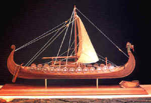
Gokstad Viking Ship
Construction Methods Page 3
On the other strakes the ribs and lashing-cleats were fitted together
and lashed with fine spruce roots. These were threaded through the
corresponding holes in the ridge on the under side of the ribs and in the
lashing cleats on the strakes.
The extreme ribs fore are made as high bulkheads, with the sides cut in
a series of little steps, fitting closely to the strakes in the planking
and nailed to them. There is a small opening in the bottom of the bulkhead
over the keel, to allow the bilge water to run through. The bulkhead aft
is also formed as a support for the rudder, as will be described later.
Far up in the bow and the stern another small bulkhead is inserted.
preserved in the Oseberg ship. In the Gokstad ship there is also a trace
of it.
From top to top over each rib is a cross-beam. The top side is
horizontally flat, while the underside forms a flat curve to give the
maximum support to the tenth strake and the adjoining strakes in the
planking. The ends are cut obliquely flush with the lines of the ship at
each rib. In the middle, the cross-beam is supported by a prop with the
lower end cleft to sit astride the rib, and the upper end mortised into
the cross-beam. There is no prop for the two ribs nearest the bow and
stern, as the ship here so narrow that no support for the cross-beam is
needed. Midship there are no props, as the cross-beams here are supported
in connection with the mast.
The cross-beams are the last of the main factors of construction
below the water line. They complete the lateral reinforcement of the ship.
At this point those parts of the structure which bear and secure the mast
had to be put in. This is perhaps the most difficult problem to solve in a
light and stipple vessel. We know nothing of the past development of this
part of the ship. All we know is that by the time of the Viking Era the
structure had found a secure and regular form, obviously the result of a
long process of trial and error by preceding generations. It is a pleasure
indeed to see how this problem was solved in the Gokstad ship.
 |
In the middle of the ship is placed a sturdy block of oak, resting on
the keel and on 4 ribs (ribs 8-11 from the stern). The old term for this
block was the crone, (a somewhat drastic image of its function in
relation to the mast). It corresponds in function to the keelson of modern
times. The crone in the Gokstad ship is 12'2" 3.75 m.) long, about 15
3/4" (40 cm.) high and 23 1/2" (60 cm.) wide at the middle,
tapering off toward the ends. It is not fastened to the keel. It is made
fast to the 10th rib from the stern by two solid knees nailed on front
each side, and by a knee on each side to the 8th and 11th rib.
Right in
front of the 10th rib, and forward of the socket for the mast that is cut
into the crone, is a strong, vertically inclining arm, grown in one piece
with the crone. The socket itself is formed with the bottom rounded
forwards so that the foot of the mast may slip into place when the mast is
raised, while aft it is cut square, to hold the mast securely when the
ship is under sail: a detail contrived with remarkable skill in order to
avoid the necessity of lifting the mast in and out when it was being
hoisted or lowered, a frequently recurring task when the ship was under
way.
The crone carries the weight of the mast, and holds it firmly in
place. The mast partner is laid over the cross-beams, bracing the mast
when it is in an upright position. The distance from the keel to the
cross-beams is very short in relation to the total length of the mast, and
the hold must be reinforced correspondingly to withstand the pressure cell
the mast when the ship is under sail. The mast partner is the largest
single piece in the entire structure, an oak block 16' 4 4/5," (5 m.)
long, extending over 5 cross-beams 7th-l2th from the stern). In the middle
it is 3' 3 2/5" (1 m.) wide and 16 1/2" thick, with a steeply
arched transverse section, sloping down towards the ends in a
characteristic, fish-tail form. This detail explains the origin of the
Norwegian expression <> for the mast partner. Each end of
the mast partner is mortised into a cross-beam, and the four intervening
beams are fitted into grooves cut out from the under side of the mast
partner. Under the mast partner there are no props supporting the
cross-beams, but the cross-beams over the 9th rib is formed like an
upended plank, supported by the rib and the crone. The cross-beam
over the 10th rib is reinforced by the crone's vertical arm.
Moreover, the mast partner is fastened to the cross=beams by knees nailed
onto it from each side. The mast partner is thus firmly secured on all
sides, and is in itself strong enough to withstand the greatest strain.
The hole for the mast in the mast partner corresponds naturally to the
opening in the crone, and continues aft as a long, uniform opening
extending to the 8th rib, so that the mast could be raised and taken down.
When the mast was raised, the opening in the mast partner was closed by a
solid plug, a flat block of oak with a rabbeted edge making a tight fit.
Directly above the floor-boards, between the 7th and 8th rib from the
stem, is a solid, pine block on each side of the deck. Each has two deep
grooves, as if they were intended to support two rather sturdy posts at a
slight incline with their ends braced against the planking. The puzzle of
their purpose has been unsolved for a long time. Mr. Nicolaysen guessed
that is was some kind of a windlass to aid in stepping the mast, but that
seems hardly probable. The explanation of Mr. Fr. Johannessen sterns more
likely, viz. that they were supports for the sprits. It is well known that
the square sail had to be stretched out with a spar on sailing into the
wind or when the wind was abeam, and this spar had to be held firmly in
place. The two pine blocks would fit this purpose very well, although it
seems strange that there Should be two grooves in each block. The
two grooves are made so that the spar could be extended at different
angles according to the direction of the wind, an arrangement which would
be of great advantage to the ship, in the opinion of Mr. Johannessen. Not
all the details can be accounted for, but everything points to the basic
correctness of Mr. Johannessen's assumption.
 |
Goto Page 4 of Viking ship
construction methods
|